I’m an automation technician currently finishing up my final semester in Electrical & Automation Technology at Eastern Maine Community College. I grew up in Maine with involvement in outdoor education, media storytelling, local economics and agriculture. I’m interested in joining a company with a professional and solutions-oriented culture looking to recruit a new technician with interests in field service troubleshooting & diagnosis, system design and advanced automation solutions.
Please check out my project portfolio below. More will be added soon.
Certifications
Electricians Helper License
State of Maine – Electricians’ Examining Board
10/14/2022 – 10/31/2024
10-hour Construction Safety and Health
Occupational Safety and Health Administration
Issued 12/19/2020
Project Gallery (click to jump to description)
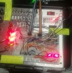

Project 1: “2-Output Temperature Controller Circuit”
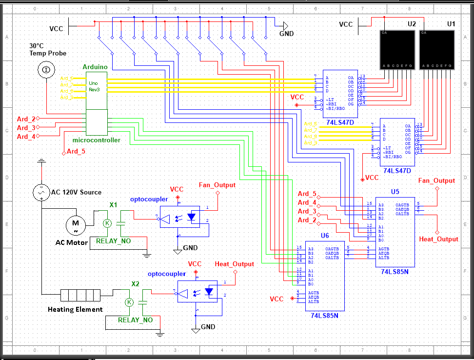
I designed a "2-Output Temperature Controller" that could be used for a lab-style application like a "fermentation cabinet" that requires a tightly controlled temperature range for specific microorganisms to thrive. We were scored based on the criteria that we utilize traditional TTL integrated circuit chips from a selection of about 30 logic ICs that had been covered throughout our Digital Electronics lab work.
For the required TTL portion, I used two 4-bit Magnitude Comparators (74ls85) that would read the incoming binary temperature data, and decide whether it was higher or lower than the chosen setpoint. I also used two BCD-to-Seven Segment Decoders (74ls47) to convert and output that binary temperature reading to two 7-Segment Displays for the operator to read. There was also a few AND- and NAND-gates with some toggle switches used to manually input the desired temperature setpoint and allow an emergency shut-off.
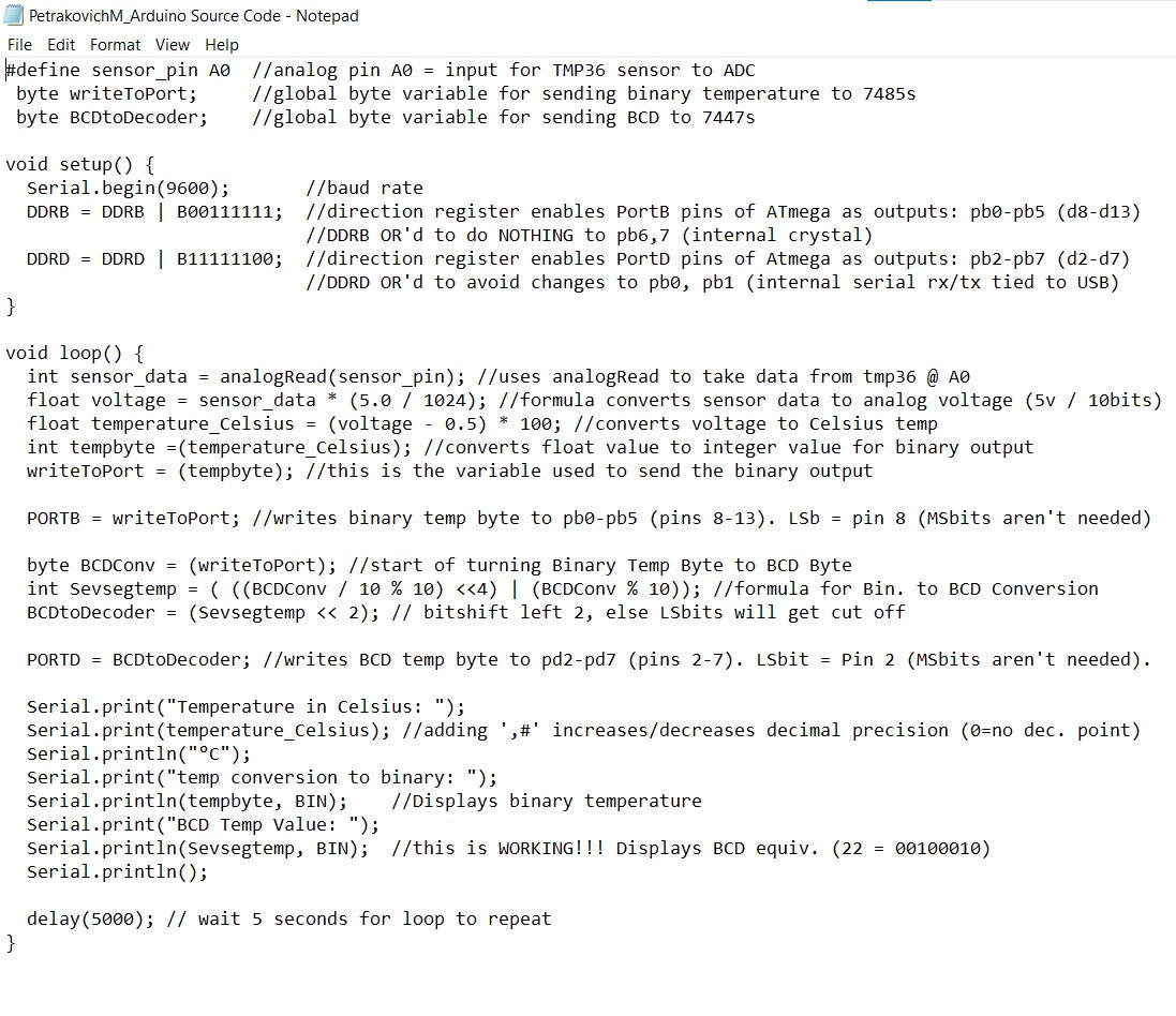
For the peripherals, I used a simple analog temperature probe (TMP36) to read the ambient temperature and an Arduino microcontroller for the analog-to-digital conversion. I could have used the Arduino for the entire project, but the assignment required us to demonstrate our understanding of traditional digital logic by using a minimum number of TTL ICs from our mandatory selection list. I had to hack together a program (using plenty of internet research) that would take the analog data and output it as both 8-bit binary and 8-bit binary-converted-decimal so that the comparators and the BCD-converters could receive the appropriate value for their functions.
Finally, the comparator was responsible for driving a pair of 120/240v opto-coupled relays that could be activated by the 5v logic and drive the two temperature control outputs: A small AC fan (the cooling element) and a red LED bulb (representing the heating element). If the temperature was within the setpoint range, neither element would be energized.
Selected Images (click for full size)
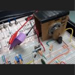
Project #2: “Temperature-Controlled Motor Fan Circuit with RPM Monitoring Output”
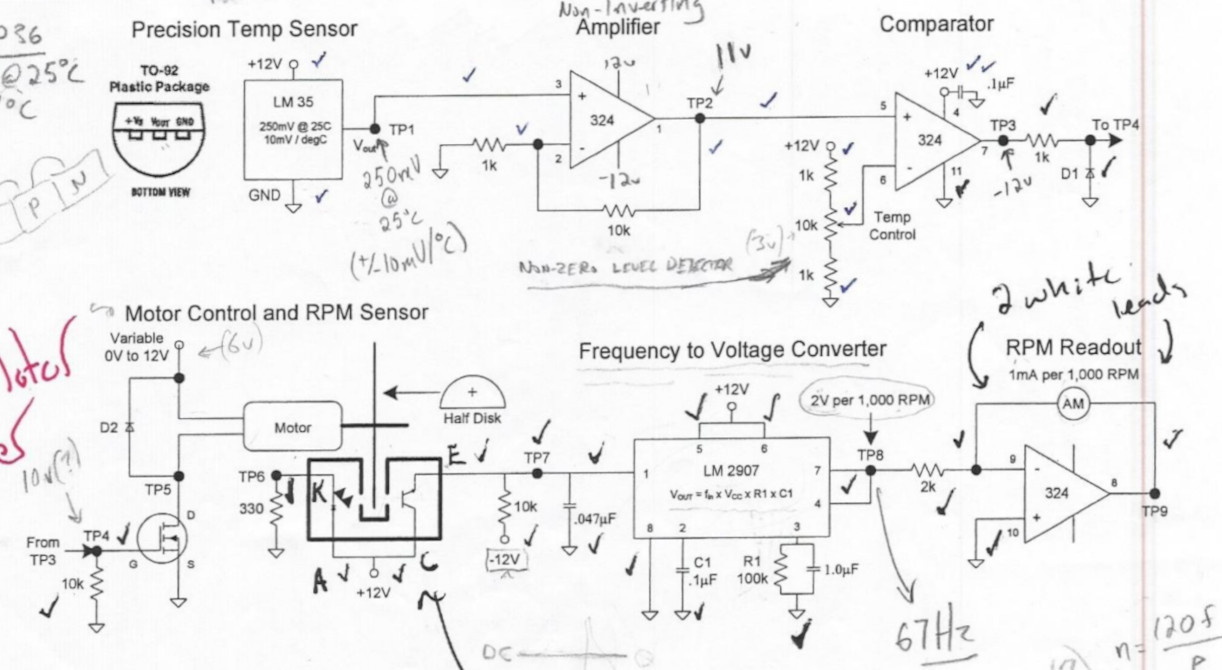
This circuit was a model for a system you might find within a piece of hardware that requires thermal monitoring to control a cooling fan. This design used both analog inputs and outputs in the forms of a sensor to read ambient temperature and two ICs to read motor RPM as both voltage and current (a method common to most older tachometers).
An analog temperature sensor (TMP36) read the ambient temperature and was input to a pair of OpAmps configured as a non-inverting amplifier and a non-zero level detector using a potentiometer for the setpoint. The initial circuit triggers a MOSFET which acts as a switch to turn the motor on or off as the temperature dictates.
The motor was equipped with a half-disc to model the fan, which was run through a slot sensor comprised of an infrared led and a photo-transistor to emit a voltage pulse with every revolution of the motor. An LM2907 Frequency-to-Voltage IC converted the pulses into a voltage output (~2v/1000RPM) which was fed into a final OpAmp configured as a buffer to give an additional speed readout in milliamps (giving us 2 analog outputs for the speed reading).
Selected Images (click for full size)
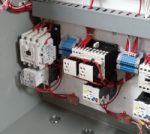
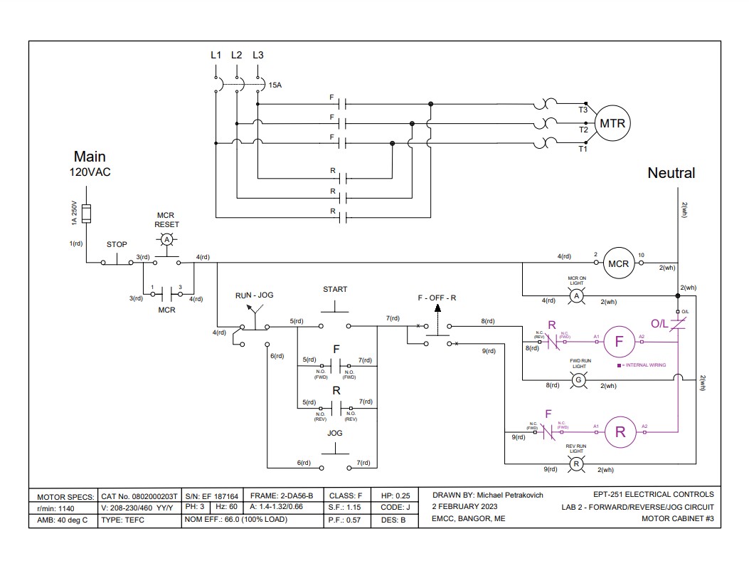
Project #3: “Forward-Reverse Run-Jog Motor Control Circuit”
The objective was to create a basic motor control circuit with forward and reverse operation and in either 'run' or 'jog' mode. The task included circuit schematic design and construction with emphasis on clean wire routing and termination, clear labelling and documentaion, and the circuit operating with the first powered demonstration.
The 208VAC 3-phase motor was directly energized by a forward-reverse motor starter triggered by a master control relay and operated by push-button and selector switch inputs at the panel. LED indicators were used as outputs to show the operating mode.
The circuit had to operate in either run or jog without the opposing mode functioning ("jog" would not work while in "run-mode", and vice-versa).
Selected Images (click for full size)

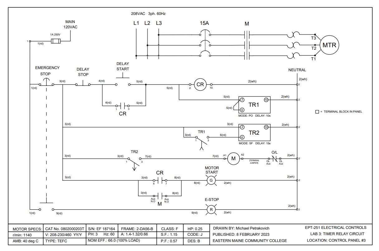
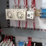
Project 4: “Timer-Relay Delayed Start/Stop Motor Control”
A simple timer-relay motor control circuit utilizing 2 timer relays for a delayed start and delayed stop sequence. We were tasked with designing the ladder diagram that would operate the circuit as specified with a 10-second on-delay and 15-second off-delay motor control sequence. The circuit could represent a simplified model of a motor that requires peripheral sequence checks before energizing/de-energizing the motor.
The circuit utilized two Allen-Bradley Timer Relays in an On-Delay and Off-Delay Configuration to provide the delayed-start and delayed-stop sequence. A single control relay served as a master control relay for the circuit. The motor was powered by a 3-phase 208VAC motor starter and operated by pushbuttons on the panel. LED indicators were used for the start-sequence and for the emergency stop.
Selected Images (click for full size)